What is phase in audio? 5 ways to address phase issues
Learn what phase is in audio and music production and look at five ways you can address phase issues in your mix to increase clarity.
Like headroom, the concept of phase is one of those core, foundational concepts in audio engineering that is often misunderstood. If the Wikipedia definition of phase has left you scratching your head, or you’ve been wondering why phase is measured in degrees, or what the heck someone means when they say, “sounds like you’ve got some phase issues going on in your drums,” you’ve come to the right place.
In this piece, we’re going to untangle exactly what phase is, when and why it can be beneficial vs. problematic, and how to deal with it when it falls into the latter category. You also have my word that I’ll keep it math-free and use good visual and sonic examples where possible. So let’s dig in and sort out this phase issue once and for all.
What is phase in audio?
In the purest sense of the term, “phase” describes a position, measured in degrees, within a single cycle of a sine wave. Even that is dense though, so let’s try to break it down a bit more.
First of all, what does measuring a sine wave in degrees even mean? This is one of those concepts that’s easiest to demonstrate visually, so let’s take a look at a little gif and tease this idea apart.

Above, on the left, we see one cycle of a sine wave, constantly refreshing itself. On the right, we see what’s known as a phasor. Phasors are math-y things that we’re not going to worry about too much other than to say, they’re basically just an arrow that rotates in a circle.*
One thing we hopefully all remember about circles is that they encompass 360° of rotation, and so as the arrow spins, we can describe its position in degrees—as marked around the dashed circle, above. If we then tie the vertical location of the tip of the arrow to the sine wave—illustrated by the dashed line connecting the two—we can infer the position within the wave cycle, measured in degrees, according to the arrow’s angle.
*Yes, technically the phasor should be rotating counterclockwise, don’t @ me. Also, if you know that, what are you doing here?
In essence, this allows us to describe fractions of a waveform cycle with a high degree of detail. 90° is one-quarter of a cycle, 180° is half a cycle, 7° is seven-three hundred sixtieths of a cycle. On its own though, this ability to precisely describe position within a waveform doesn't mean much. When we start looking at two waveforms of the same frequency, however, being able to talk about and measure the phase relationship between them becomes crucial.
Phase vs. polarity
Before we discuss that in detail though, I’d like to review one other related concept: polarity. Whether it’s in your DAW or on a plug-in, you may have noticed the “Ø” symbol at one point or another. People often call this a “phase switch” and will say it’s used to “flip the phase.” If we’re being accurate though, this is rightly called a polarity switch, and while reversing—or flipping—polarity looks an awful lot like a 180° phase shift, they are not strictly equivalent.
Simply, polarity reversal is exactly like swapping the cables going into the positive and negative terminals on your speakers. A signal that is used to make the speaker cone push out now makes it pull in, and crucially, this operation occurs instantaneously: the exact moment it would've pushed out, it now pushed in. A 180° phase shift, on the other hand, means that all frequencies have been delayed—or shifted in time—by half a cycle. As with a polarity flip, what was once “out” is now “in”, however, it’s also happening ever so slightly later in time.
This time shift gets at the core of what phase manipulation is, and is important not only in understanding the impact of phase issues in music production but also in applying remedies. More on this, next.
Follow along and fix phase issues in your audio with a free demo of
![]()
![]()
RX 11 Advanced
Phase in action: how and why
Measuring and talking about phase relationships becomes really important when two or more signals are involved. This is mainly because the phase relationship between two signals has a strong impact on how we perceive them collectively, in several ways. To examine this, let’s look at our friend the sine wave again in a few different phase relationships with a twin sine wave.
First, here they are “in phase” with each other. In other words, there is no phase offset between them. Notice how the peaks and troughs of both waveforms align.

Sine gong, in phase
Next, let's look at a 90° offset. Here, the peaks and troughs of one waveform will align with the zero crossings of the other.
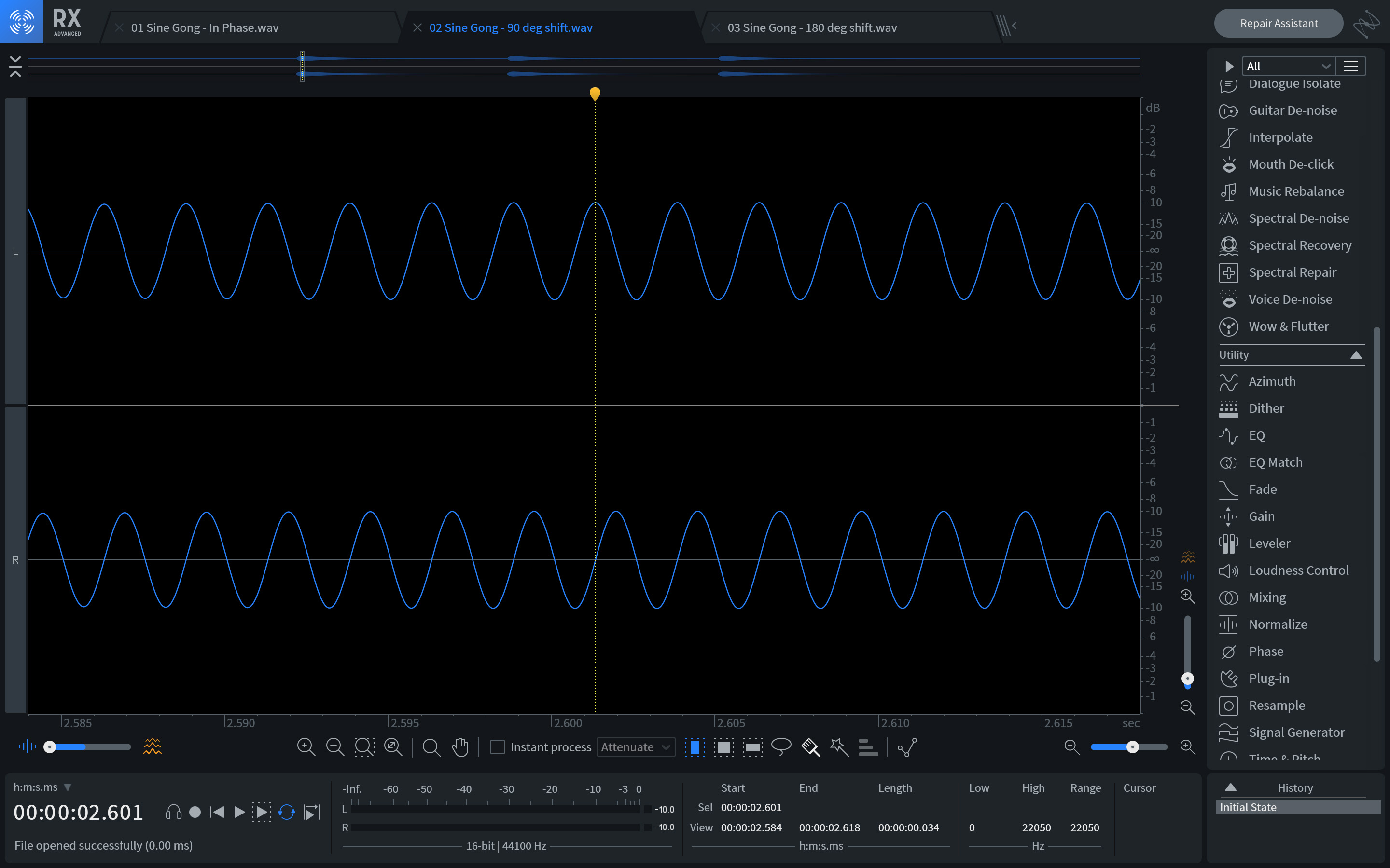
Sine gong, 90 degree shift
Finally, here’s a 180° phase offset in which the peaks of one waveform align with the troughs of the other.
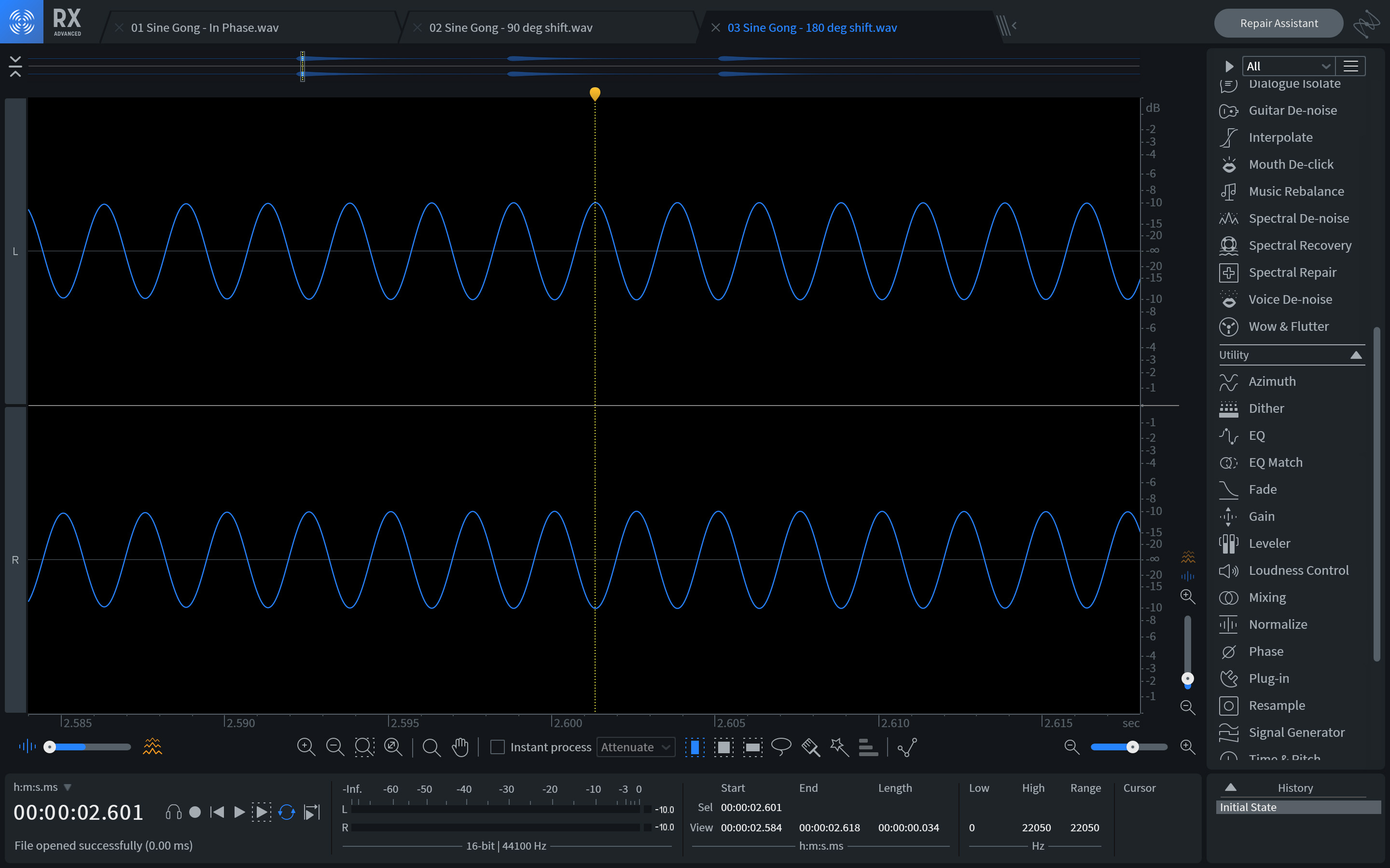
Sine gong, 180 degree shift
Phase-shift in stereo
Now that we know what different degrees of phase shift look like at a specific frequency, let’s talk about the sonic impact of each.
First, know this: the sonic quality of each example will depend entirely on whether the twin sine waves are played in stereo, or summed to mono. Said another way, the degree to which they share a pan position in a mix is going to radically change the way we hear them.
First, let’s discuss the impact in stereo, where the top waveform is panned hard left and the bottom one is panned hard right. Whether you’re listening on speakers or headphones is also going to have an impact, so let’s look at—and listen to—what to expect in each case.
The in-phase pair is going to sound as if they’re one, dead-centered source. On speakers, this should sound like it’s directly between the two speakers—often called the “phantom center”—whereas in headphones it will probably sound like it’s in the center of your head.
When the right channel is shifted 90°, something interesting happens. In both speakers and headphones, you will likely notice that the transient onset of the gong sounds like it's coming slightly from the left, while the tail sounds somewhat diffuse—as if it doesn’t have a definite position.
This is very much related to how humans hear in stereo. Our ear-brain system uses a number of cues to determine which direction a sound is coming from, but the phase relationship between both ears is a big part of it. If a sound arrives at one ear before the other, it usually means the source of the sound is closer to that ear, and so our brain judges it as coming from that direction. This is important, and something we’ll touch on more, later.
What if the right channel is shifted 180°? Again, you’re likely to perceive it as coming from the left, since the left channel now leads the right by a full half-cycle, but there’s something else odd about this relationship. On speakers, if you rotate your head, you may find that the apparent position of the sound seems to move around, while on headphones it may sound entirely diffuse, or even like it’s behind you!
Phase-shift in mono
In mono, something very different happens. As a reminder, mono basically just means that we’re adding the two signals together. This can happen for a few different reasons. For example, maybe a stereo signal is being played back on a mono system—like certain phones, smart speakers, or PA systems—or perhaps two signals just share the same pan position in the mix.
When this happens, in-phase signals add together to amplify each other, while signals that are 180° out of phase cancel each other out entirely. In between 0° and 180° of phase shift, we get varying amounts of amplification and cancellation. For example, at 90° the mono signal is 3dB lower compared to the in-phase sum.
This is going to be important when we start to discuss addressing phase issues in a mix, but it also relates to one other important concept that I’d like to look at first: comb filtering.
Phase-shift vs. time-shift
Based on what we’ve discussed so far, you would be completely justified in thinking, “Hold on. It sounds like you’re basically describing time-shifting – or very short amounts of delay,” and in a way, you’d be right. When we’re just talking about a single frequency, varying degrees of phase-shift are indistinguishable from the corresponding time delays. However, while our 400 Hz sine gong made for easy audio and visual examples, we don’t usually listen to music composed of single frequencies.
When we’re dealing with a wideband signal – in other words, music, with frequency content between roughly 20 and 20,000 Hz – a time delay between two signals is going to correspond to different amounts of phase-shift at different frequencies.
For example, imagine we shift the right channel 2.5 ms behind the left channel. What sort of phase shift will this look like at different frequencies? Let’s pick a few and analyze them:
- At 100 Hz, one cycle of the waveform – also known as its period – is 10 ms. 2.5 ms is just one-quarter of this, so that means the inter-channel phase shift is just 90°.
- If we double the frequency to 200 Hz, that means the period is halved to just 5 ms. Since 2.5 ms is one-half of the period, the inter-channel phase shift is now 180°, and should these two channels be added together we’ll get a complete cancellation here.
- What if we keep going? At 400 Hz, the period is 2.5 ms – the same as our time shift – so that’s 360° of phase shift, in other words back in-phase albeit one cycle behind. At 600 Hz we’re at 540° – a full cycle + 180° – so we get another cancellation. At 800 Hz we’re back to in-phase, and this pattern continues, switching between in-phase and out of phase every 200 Hz, all the way on up.
This pattern is known as “comb filtering” due to its characteristic frequency response, and it’s not generally an especially desirable sound. The image below may give you a clue as to how it got its name, and here’s a clip of its characteristic sound when applied to some white noise.

Comb filtering
This highlights an important distinction though: while phase and time are certainly interrelated—and interdependent—they are not the same thing, nor can they always be thought of or addressed interchangeably.
How to fix out of phase audio
Ok! With an admittedly large amount of theory out of the way, let’s take a look at when and how we may—or may not—want to address phase issues in a mix. First, I think it’s important to take a moment to point out that not every phase issue is a phase issue. What do I mean by that?
Well, as we discovered earlier, phase differences between left and right channels can be an important part of how we perceive stereo placement above and beyond simple level panning—although that certainly plays a role too. Whether we create these phase differences intentionally or they’re simply part of a stereo recording, trying to correct them entirely may rob us of much of the spaciousness they create.
As another example, analog-style—a.k.a. minimum phase—EQ inherently creates phase-shift around different types of filters. This is part of the characteristic sound of this type of EQ, and while linear phase EQ certainly has its place, the types of tone-shaping moves we tend to like analog-style EQ for often don’t sound right without the accompanying phase-shift.
Finally, before the modern era of the digital audio workstation, which has allowed us to see waveforms in high definition, there could be phase-shift all over the place that we would never know about if it didn’t cause an audible issue. For example, the very process of recording to and playing back from tape causes about a 22° phase shift—it’s simply part of going from voltage in a wire to magnetic flux on tape.
When to address phase issues
All that said, there are absolutely times when we may want to address phase issues during the production and mixing process, and they tend to fall into a few categories.
First, any time a source is recorded to multiple channels. This could be the result of multiple mics being used on the same source, or a combination of mics and a DI box on the same source. Common examples of this would be a multi-mic'd drum set, multiple mics on a guitar cabinet, or a mic and DI on a bass cabinet and amp.
The issue here is that since it’s very difficult to position multiple mics exactly the same distance from a source—and nigh impossible on a drum set where there are multiple mics and multiple sources—there are bound to be slight timing differences between mics. This is simply because sounds take a little longer to travel the greater distance to one mic than the other.
If these recorded channels share a similar pan position—as in a guitar, bass, snare, or kick drum—this can lead to comb filtering and potentially cancellation or dips in level at certain frequencies or notes. If they’re part of a stereo pair—as in drum overheads—this can affect where the center of the stereo image is. In any event, these scenarios are good candidates for alignment to avoid phase issues.
Second, if you’re using drum samples, whether to augment the live drum sound or while stacking samples to create a new drum sound. The potential issue here is that since these samples don’t originate from the same physical source, they may have very different frequency components with different phase relationships to each other. What sounds good on its own can often end up sounding hollow, or weak, when blended with a similar sound. Here, again, we can use some tricks to get the most out of our samples.
Third, and lastly, if you’re doing any parallel processing, or processing similar channels—for instance, a top and bottom snare mic—in different ways. Often, this is a non-issue, but when it becomes an issue it can be difficult and frustrating to track down. We’ll get into this below.
How to address phase issues
There are a number of ways we might choose to address phase issues as they crop up in a mix, so let’s look at five of them in some detail, and tie them to the three scenarios outlined above. First, we’ll look at one of the most common instances: a multi-mic'd drum set. As an example, we’ve got a recording of a kit with nine mics. This is a nice middle-of-the-road example, as you can certainly record a kit effectively with fewer mics, but I’ve also seen recordings with many more channels.
One of the distinct challenges with drums is that, as mentioned above, not only do you have quite a few mics, but each drum is essentially its own sound source. As a result, a lot of what’s possible in terms of time alignment to reduce phase issues is dependent on how the mics were originally set up.
For example, while it may be possible to align the overheads to each other, and the resulting pair to the kick, it may simply be a geometric impossibility to align the overhead pair to both the snare and kick. As such, it’s important to have a strategy of what to prioritize when you start working on a recording like this. Let’s walk through how we might do that.
Technique 1: Nudge the waveform
To start off, I usually like to make sure any mics on an individual drum are working together. That includes things like Kick In, Kick Out, and Sub Kick, or Snare Top and Snare Bottom. Sometimes, for these kinds of adjustments, simple is best. Let’s take a look at the recording we’re working with.

Kick and snare alignment, original recording
Here, we can see a number of things! First, the transient of the kick and sub kick has about a 90° offset. Since low frequencies have longer wavelengths, it’s entirely possible to effectively align the kick mics by simply dragging or nudging the waveform. To add some precision to this, you can try the following.
Locate your cursor at an easily identifiable point—perhaps a peak, or a zero crossing—on the channel that happens earliest in time, in this case, the Kick channel. Then, drag any later occurring channels back so that the same point aligns. Another neat trick is to pan one mic hard left and the other hard right, and then put either
![]()
![]()
Insight 2
![]()
![]()
Ozone Imager V2
First, nudge or move the out of time channel until the vertical correlation meter on the right gets as close to +1 as you can manage. This should make a very nearly straight line on the Polar Sample or Polar Leve scope—I find the latter easiest to use. Then, if desired, adjust the clip gain of the track until the Polar Sample or Level scope points straight up, indicating that the levels of the channels are balanced. Once complete, return the pans of the channels you’re aligning to their original position.
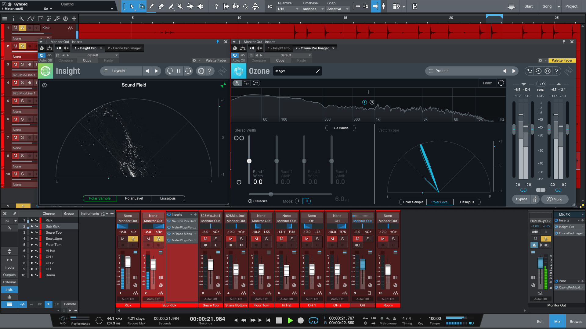
Using Insight or Ozone Imager for alignment
Of course, you may want to change the balance between the channels anyhow, so this last step is not as crucial. While this trick is particularly helpful when manually adjusting the timing between two channels, it can also be used on any of the following techniques.
Technique 2: Micro-delay plug-ins
Whether you need more precise control than dragging and nudging offers, or you just want to leave the recorded audio in its original location, micro-delay plug-ins offer another option for precise time alignment. There are a handful of these types of plug-ins out there, some free, some with waveform views, and some that allow you to delay either forward or backward in time.
If this seems more up your alley, check to see if your DAW includes such a plug-in, or if the capability might be built right into the mixer channel. Many DAWs offer this capability, but if yours doesn’t, a third-party plug-in will do the trick. It’s worth noting that iZotope Relay and Neutron both have time-adjusters. Relay has them here:
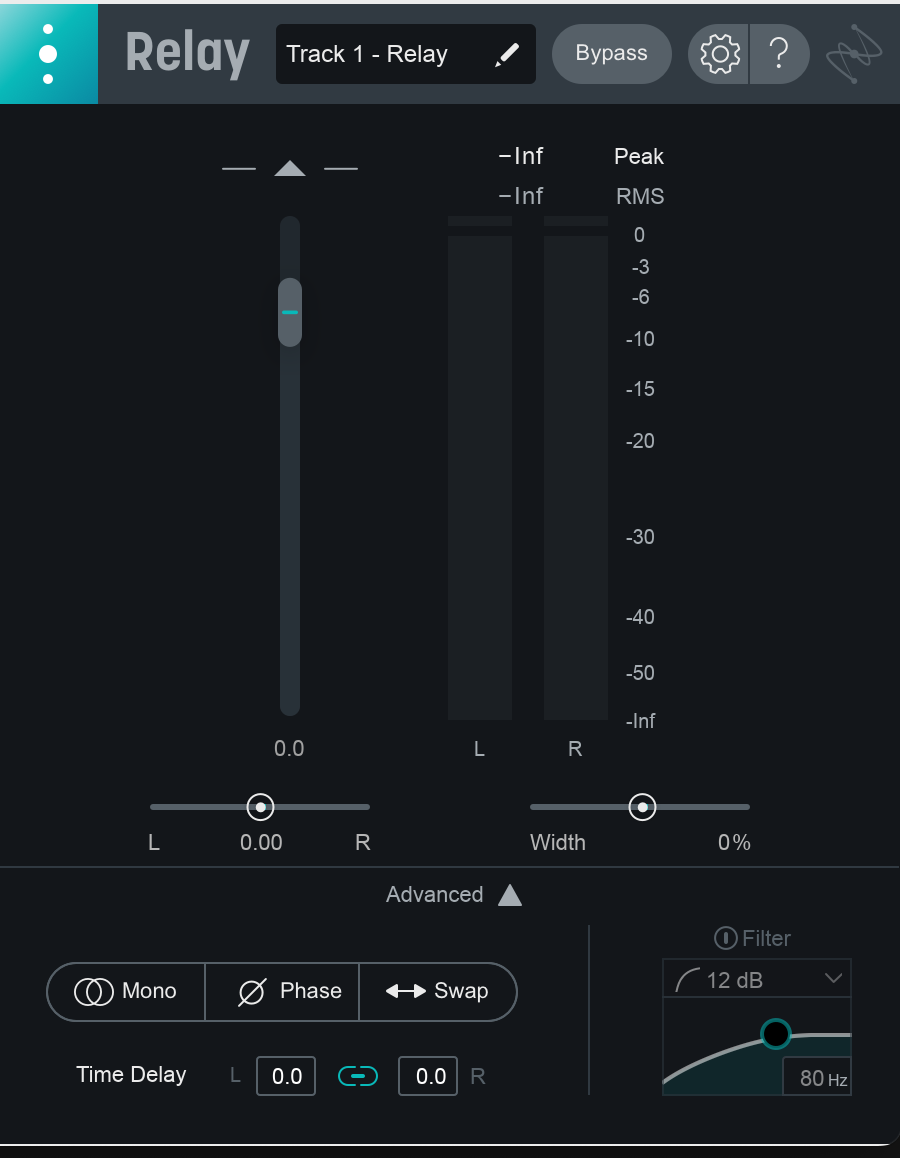
Relay
While Neutron has them here, tucked away in the preferences:

Neutron 5
This article references a previous version of RX. Learn about RX 11 and its powerful new features like Adaptive Dynamic Mode in RX De-hum, improved Spectral Recovery, the new Repair Assistant, and more.
Technique 3: RX or Neutron modules
Did you know that RX 11 Advanced has modules that can help with these sorts of tasks? Let’s start by looking at how we might align a pair of overheads, and then look at how RX could help us when layering samples.
Once I have all the individual mics for each drum aligned together, I usually like to look at the overheads. While you can certainly use either of the techniques mentioned above, the Azimuth module in RX provides an easy and accurate way to align stereo pairs of mics. If your overheads—or other stereo pair—are already a stereo file, you’re ready to get started. If not, you can either use your DAW to export them as a stereo file or copy and paste each file into a new stereo file in RX.
Once the stereo file is open in RX, zoom in to find the drum you’d like to place in the center of your stereo image—I usually choose the kick or snare. Make a selection around the waveform of that drum, open the Azimuth module, and click the “Suggest” button. This will calculate the optimal delay and level adjustment to align the stereo pair. You can then render this setting to the entire file, export it, and bring it back into your mix session.